04.08.2026 15:43
Correct gate valve selection requires more than determining the nominal diameter and pressure rating. The face-to-face length, overall height, flange outside diameter, bolt-hole arrangement, handwheel diameter and approximate weight must also be compatible with the piping system.
Gate valve dimensions may vary according to the body pattern, pressure class, stem design, flange standard and operating mechanism. For installation and replacement projects, the most critical dimension is the face-to-face length (L).
Dimension Symbols
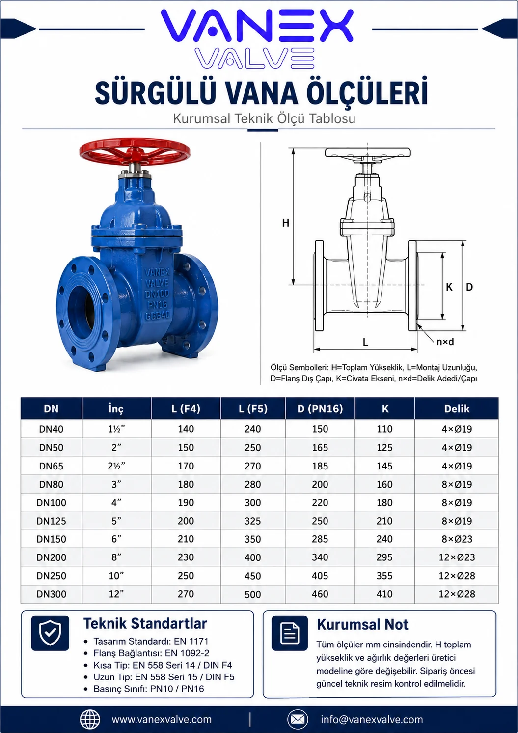
Symbol Technical description
DN Nominal valve diameter
L Face-to-face installation length
H Overall valve height in the closed position
H1 / H3 Auxiliary body, stem or actuator height
D Flange outside diameter
K Bolt circle diameter
n × d Number of bolt holes × hole diameter
W Handwheel outside diameter
F Stem head or operating connection dimension
kg Approximate net valve weight
F4 Short Pattern Gate Valve
F4 gate valves have a compact face-to-face length in accordance with EN 558 Series 14 / DIN F4. They are suitable for pump rooms, treatment plants, mechanical installations and applications where installation space is limited.
F5 Long Pattern Gate Valve
F5 gate valves have a longer body in accordance with EN 558 Series 15 / DIN F5. They are generally preferred for replacing existing long-pattern valves and for piping systems designed according to Series 15 dimensions.
Reference Face-to-Face Dimensions
All dimensions are in millimetres.
DN Inch F4 short pattern L F5 long pattern L
DN40 1½″ 140 240
DN50 2″ 150 250
DN65 2½″ 170 270
DN80 3″ 180 280
DN100 4″ 190 300
DN125 5″ 200 325
DN150 6″ 210 350
DN200 8″ 230 400
DN250 10″ 250 450
DN300 12″ 270 500
Dimension Comparison Examples
DN100
F4 face-to-face length: 190 mm
F5 face-to-face length: 300 mm
Difference: 110 mm
DN150
F4 face-to-face length: 210 mm
F5 face-to-face length: 350 mm
Difference: 140 mm
DN200
F4 face-to-face length: 230 mm
F5 face-to-face length: 400 mm
Difference: 170 mm
For this reason, an existing valve must not be replaced by checking only DN and PN values. The F4 or F5 body pattern must also be verified.
Flange Dimensions
For correct installation, the following flange dimensions must match the piping system:
Flange outside diameter
Bolt circle diameter
Number of bolt holes
Bolt-hole diameter
Flange thickness
Sealing face
PN10, PN16 or PN25 pressure rating
Flange connections are generally manufactured in accordance with EN 1092-2. In some nominal sizes, PN10 and PN16 flanges may have a common drilling arrangement. However, the hole pattern may differ, particularly from DN200 upwards.
The required pressure class must therefore be clearly stated as, for example, DN200 PN10 or DN200 PN16.
Overall Height
The overall height, indicated by H, is measured from the valve base or pipe centreline to the highest point of the handwheel or actuator.
This dimension may vary depending on:
Rising or non-rising stem design
Bonnet and body construction
Handwheel diameter
Gearbox or actuator
Position indicator
Extension spindle
Manufacturer-specific design
Unlike the standard face-to-face length, overall height, handwheel diameter and weight may vary between manufacturers and product series.
Gate Valve Selection Procedure
Determine the nominal pipe diameter.
Check the system operating and test pressures.
Select the required PN10, PN16 or PN25 rating.
Measure the existing flange outside diameter and drilling arrangement.
Check the available face-to-face installation distance.
Select F4 short pattern or F5 long pattern.
Provide sufficient operating and maintenance clearance.
Check the free space required for handwheel operation.
Recalculate the overall dimensions when using a gearbox or actuator.
Approve the current technical drawing before ordering or manufacturing.
Applicable Technical Standards
Subject Reference standard
Valve design EN 1171
Valves for water supply EN 1074-1 / EN 1074-2
Face-to-face dimensions EN 558 Series 14 or Series 15
Short pattern designation DIN F4
Long pattern designation DIN F5
Flange connection EN 1092-2
Pressure testing EN 1074 / EN 12266
Typical Applications
Drinking-water networks
Water treatment plants
Pumping stations
Fire-fighting systems
Irrigation systems
Industrial water lines
Wastewater systems
Building mechanical installations
Municipal infrastructure projects
Manufacturing plants
Corporate Product Description
VANEX VALVE gate valves are flanged flow-control solutions developed for industrial systems, infrastructure projects, water-distribution networks and fire-protection installations.
F4 short-pattern and F5 long-pattern alternatives provide compatibility with different installation distances. During valve selection, the nominal diameter, pressure rating, flange drilling, face-to-face length and overall height must be evaluated together.
The measured installation distance in the pipeline must correspond exactly to the L dimension shown on the approved product drawing. Selecting the wrong F4 or F5 pattern may require pipe cutting, welding, adaptors or additional fittings.
Technical note: The stated F4 and F5 values represent standard face-to-face dimensions. Flange drilling, overall height, handwheel diameter and product weight may vary according to pressure class and product design. The latest VANEX VALVE technical drawing must be checked before ordering.